
Quick Answer & Key Takeaways
Preloading tapered roller bearings in heavy-duty axles and industrial reducers involves setting a controlled initial internal axial load to eliminate internal clearance, maximize system rigidity, and optimize fatigue life under dynamic operating conditions. Proper preload prevents roller skidding under light load and eliminates excessive deflection under heavy combined radial and axial thrust forces. Because thermal expansion during high-speed or heavy-torque duty reduces internal clearances, calculating preload requires balancing mounting tightening forces against target running torque, operating temperature differentials, and elastic housing deflection. Plant maintenance teams, gear drive design engineers, and industrial procurement managers specify precision-preloaded tapered roller bearing arrangements to extend gear mesh life, prevent edge-loading stress concentration, and avoid premature subsurface spalling in demanding drive applications.
-
Optimal Fatigue Life Range: Operating with a slight negative internal clearance (preload) maximizes rolling element load sharing and achieves peak L10h bearing fatigue life.
-
Torque-Based Setting Verification: Measuring running frictional torque ($M_r$) provides a reliable indirect verification of correct internal axial preload forces during factory assembly.
-
Thermal Differential Accommodation: Calculations must factor in inner ring thermal expansion to prevent excessive tightening and thermal lockup during full-load operations.
-
Enhanced Gear Mesh Alignment: Controlled preloading restricts pinion shaft angular tilt, preserving correct hypoid and helical gear tooth contact patterns under heavy torque.
What Is Bearing Preload and Why Is It Critical for Heavy Drive Axles?
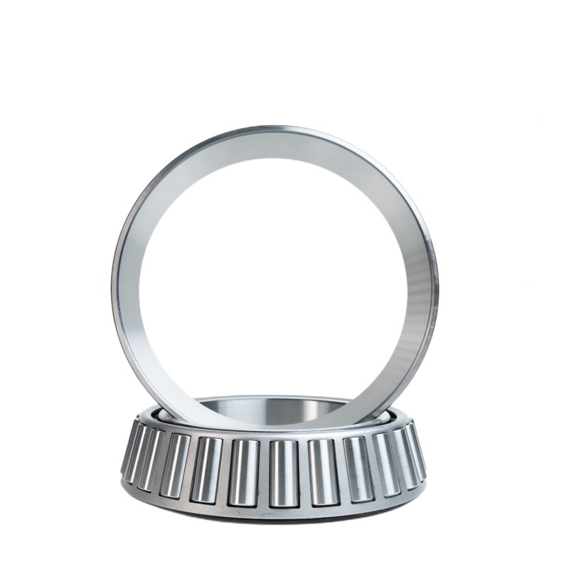
Bearing preload is the application of a permanent axial force to a tapered roller bearing pair during installation, establishing negative internal axial clearance before external operating loads are applied. Unlike standard radial bearings that require positive clearance to allow free rotation, tapered roller bearings operate on converging contact lines where internal contact angles allow radial and axial forces to interact directly.
In heavy-duty axles, planetary final drives, and industrial gear reducers, variable torque loads cause structural elastic deflection across shafts and housing walls. Without proper axial preload, pinion shafts shift under torque surges, causing localized edge loading on gear teeth and promoting roller skewing inside the bearing raceways. Preloading eliminates internal play, ensuring all conical rollers maintain continuous contact with inner and outer raceways, which distributes operational forces evenly and maintains precise gear alignment.
Engineering Step-by-Step: Calculating Preload Forces and Running Torque
Setting the correct preload requires converting desired axial clamping force into measurable assembly parameters, such as axial shim thickness or rotational running torque.
Step 1: Determine the Optimum Axial Preload Force ($F_{a0}$)
The optimum axial preload force depends on the maximum applied external radial load ($F_r$) and axial thrust load ($F_a$). For a typical paired face-to-face (DF) or back-to-back (DB) tapered roller bearing arrangement, the baseline mounting preload force ($F_{a0}$) is generally calculated using the empirical load distribution factor:
Where $Y$ is the ISO thrust factor (typically ranging from 1.2 to 2.0 depending on the contact angle $\alpha$). To prevent roller unloading on the un-loaded row under peak thrust, $F_{a0}$ must exceed the minimum dynamic threshold required to maintain continuous roller-raceway engagement.
Step 2: Calculate Frictional Running Torque ($M_r$)
Because direct measurement of internal axial forces inside a sealed axle housing is impractical on production lines, assembly engineers verify preload by measuring rotational running torque ($M_r$). The relationship between axial preload force ($F_{a0}$) and frictional torque is expressed through the following formula:
Where:
-
$M_r$ = Running torque (Nm)
-
$\mu$ = Frictional coefficient for preloaded tapered roller bearings (typically $0.0018$ to $0.0025$)
-
$F_{a0}$ = Applied axial preload force (N)
-
$d_m$ = Bearing mean diameter ($d_m = \frac{d + D}{2}$, in meters)
Step 3: Adjust for Thermal Expansion and Structural Elastic Deformation
During continuous heavy-duty operation, inner rings mounted on rotating pinion shafts run hotter than outer rings mounted in ambient-cooled housing walls. This thermal gradient ($\Delta T = T_{inner} – T_{outer}$) causes differential radial expansion ($\delta_t$), which increases effective running preload:
Where $\alpha_s$ is the thermal expansion coefficient of bearing steel ($12 \times 10^{-6} / ^\circ\text{C}$) and $\theta$ is the raceway contact angle. Assembly calculations must deduct this thermally induced interference from the cold mounting setting to avoid thermal run-away and raceway burning at operating temperatures.
Comparative Performance Analysis: Under-Preloaded, Correctly Preloaded, and Over-Preloaded Bearings
Achieving the correct preload setting requires balancing geometric alignment against heat generation. The comparative operational parameters across varying preload states are outlined below.
Under-preloaded conditions occur when internal clearance remains positive during operation. Under heavy axle torque, the un-loaded roller zone allows rollers to skew, resulting in high edge-loading stresses, localized cage wear, gear mesh misalignment, and reduced system stiffness. Operating life drops significantly below theoretical L10h ratings due to stress concentration on a reduced number of active rollers.
Correctly preloaded conditions maintain a slight negative internal clearance under full thermal equilibrium. All conical rollers share the radial and axial load vectors evenly across the raceway contact arc. Frictional torque remains stable, heat dissipation reaches equilibrium with cooling oil flow, gear tooth alignment is preserved under shock loads, and bearing fatigue life reaches its theoretical maximum (100% L10h capability).
Over-preloaded conditions occur when excessive shim clamping or uncompensated thermal expansion forces rollers tightly against raceways. Frictional torque spikes rapidly, generating excessive operational heat that breaks down lubricant film viscosity. The resulting metallic contact causes rapid surface fatigue, micro-spalling, and catastrophic thermal seizure within short operating durations.
Setting and Verification Methods for Industrial Assembly Lines
Translating calculated values into consistent factory production requires standardized mounting protocols:
-
Torque-to-Rotate Method: Mechanics rotate the pinion shaft while tightening the locknut or end-plate bolts until a pre-determined running torque limit is registered on a digital torque wrench. This method accounts for manufacturing tolerances across housings and shafts.
-
Precision Shim Pack Selection: Dial indicators measure total axial endplay in the loose assembly. A shim pack equal to measured endplay plus calculated axial compression thickness ($\delta_a$) is installed between the housing shoulder and outer ring flange.
-
Deformable Spacer (Crush Sleeve) Assembly: Commonly used in high-volume automotive and light truck axles, a collapsible metal spacer deforms predictably under locknut torque, establishing target preloads without manual shimming.
-
Hydraulic Drive-Up Setting: Heavy industrial gearboxes utilize hydraulic nuts equipped with pressure gauges to apply exact axial thrust forces directly to bearing inner rings before locking mounting collars into position.
Frequently Asked Questions (FAQ)
What is the difference between axial endplay and bearing preload?
Axial endplay refers to positive internal clearance, where a shaft can move freely back and forth along its axis by a measurable distance. Bearing preload is negative internal clearance, where rollers are clamped tightly under continuous axial force even when no external working load is applied.
How does incorrect preload affect hypoid gear life in drive axles?
Incorrect preload allows the pinion shaft to shift under load. Under-preloading causes the pinion gear to deflect away from the ring gear, concentrating forces on the gear tooth tips and causing premature gear tooth breakage or severe whining noise. Over-preloading causes excessive heat that breaks down gear oil additives.
Why does running torque increase after installing axle oil seals?
Axle radial lip seals create mechanical friction against shaft journal surfaces. When measuring bearing preload via running torque, technicians must measure bearing rotation torque prior to seal installation or add the seal drag torque allowance to the calculated target value.
Can oil viscosity affect running torque measurements during assembly?
Yes, high-viscosity assembly greases or cold gear oils increase hydrodynamic shear resistance, elevating measured running torque. Preload setting measurements should always be conducted using clean ISO VG 32 or VG 68 calibration oil at room temperature.
How do engineers compensate for housing deflection under load?
Heavy axle housings flex under extreme wheel loads. Machine designers perform Finite Element Analysis (FEA) to calculate housing expansion at full payload, increasing cold static preload settings so that operational housing stretch relaxes the bearing pair into the optimal negative clearance window.
Post time: Sep-30-2026