
Split bearings represent a fundamental engineering solution to one of the most persistent challenges in heavy industrial operations: bearing replacement on long or trapped shafts without dismantling adjacent equipment. Unlike solid bearings that require complete shaft disassembly, split bearings feature a two-piece inner and outer ring design that allows installation directly around the shaft. This design delivers documented mean time to repair (MTTR) reductions of up to 70% and addresses critical safety concerns in mining, steel, cement, and power generation applications . For B2B procurement and engineering teams, the value proposition extends beyond installation convenience to measurable reductions in downtime and maintenance exposure.
Key Takeaways:
- Split bearings reduce MTTR by up to 70% by eliminating shaft disassembly requirements
- The design enables rapid replacement in trapped positions between gearboxes and motors
- Mining, steel, cement, and fan applications represent the primary adoption sectors
- Proper sealing and lubrication selection is critical to achieving rated service life
- Retrofit opportunities exist for converting existing solid bearing installations
What Defines a Split Bearing?
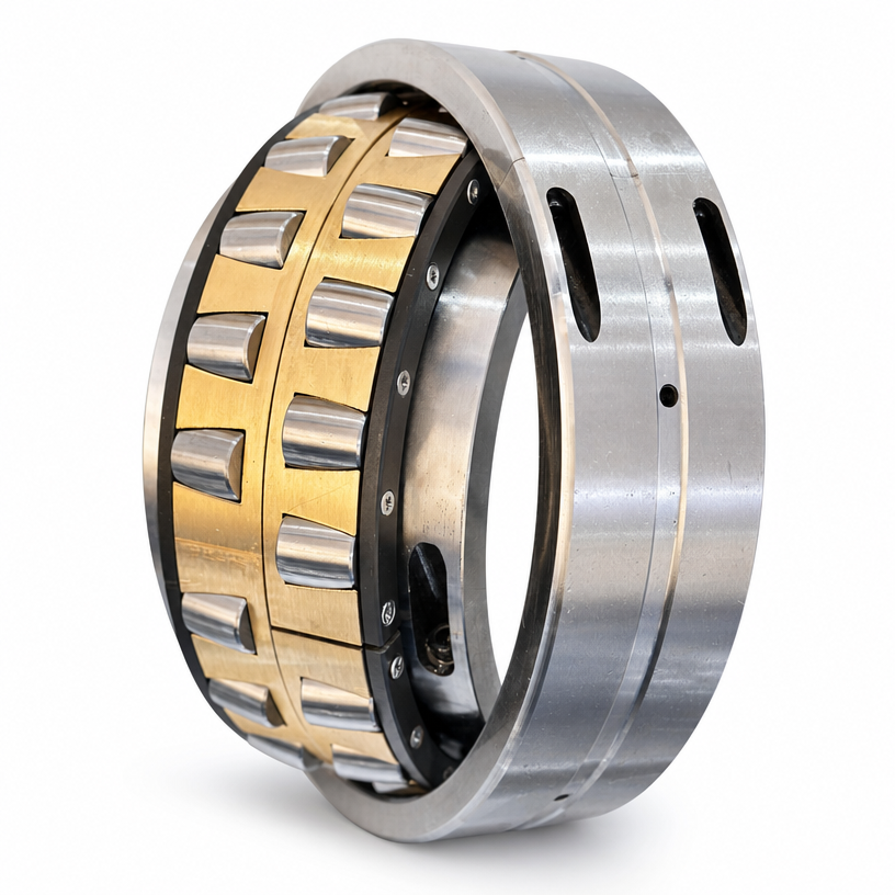
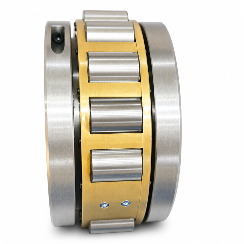
A split bearing is a rolling element bearing with a radially divided inner and outer ring. This construction allows the bearing to be installed directly around a shaft at its operating position rather than requiring the bearing to be slid over the free shaft end. The design typically incorporates a split cage assembly that secures the rolling elements, along with a clamping mechanism—commonly a split clamp ring or segmented locking device—to secure the inner ring onto the shaft with proper interference fit .
For a 120-ton converter application, split bearing designs often utilize threaded connection structures due to limited installation space, which directly impacts the bearing’s internal geometry and load-carrying capacity . This illustrates an important engineering consideration: split bearings often require customized design tradeoffs to meet specific application constraints.
The fundamental design innovation lies in the split line arrangement. In advanced split bearing configurations for demanding applications such as rolling mill work rolls, the inner ring split line is oriented at an angle (e.g., 6° to the shaft centerline) rather than parallel to the shaft axis. This angled split line allows rollers to pass across the split line more smoothly during operation, reducing impact forces and extending service life .
Core Applications Across Heavy Industries
Mining and Material Handling
Mining operations represent a primary application for split bearings, with conveyors, stacker reclaimers, crushers, and vibrating screens representing the largest adoption segments. Equipment is exposed to high concentrations of abrasive dust, heavy impact loads, and significant temperature variations . Conveyor systems demonstrate the most direct safety and maintenance benefit, as split bearings allow in-situ replacement without exposing personnel to the hazards of working in confined spaces or under suspended loads.
Steel and Metals Processing
Steel mill applications such as continuous casters, cooling beds, and rolling mills impose demanding conditions: elevated temperatures, high radial loads, and continuous operation. In converter applications, split bearings have become a preferred solution because bearing replacement on the trunnion shaft is otherwise extremely difficult and time-consuming . The ability to replace bearings without removing the converter significantly reduces downtime.
Power Generation and Marine Propulsion
Draft fans, cooling tower drives, and propulsion shafts benefit from split bearing designs that accommodate long shafts requiring support at multiple positions. For marine applications, split bearings allow replacement without dry docking or dismantling shafting systems .
Fans and Blowers
Fan applications account for approximately 40% of split bearing deployments . The low friction characteristics of cylindrical roller designs make them suitable for fan applications operating at speeds up to 3,600 rpm for shaft diameters up to 3 inches, even with grease lubrication rather than oil systems .
Design Considerations and Limitations
Load-Carrying Capability
The split design inherently creates discontinuities in the bearing raceways. This influences the bearing’s dynamic load rating and operational characteristics. Engineering evaluation must consider:
- Reduced roller path continuity at split lines
- The significance of maintaining proper clearance at inner ring split lines during installation—insufficient clearance compromises interference fit; excessive clearance reduces shaft support
- Clamp ring design that provides both axial location and cage alignment
Sealing Requirements
Dust and contamination represent the primary cause of split bearing failure in heavy industrial applications . For mining and aggregate applications, multi-stage labyrinth seals with compressible O-ring interfaces provide effective contamination exclusion. When oil lubrication is specified, attention to seal design is critical as split-type seals typically experience higher leakage rates than their solid counterparts .
Lubrication Strategy
Lubrication selection significantly influences split bearing performance and service life. Key considerations include:
- The use of high-viscosity, tacky lubricants that resist purge from the bearing cavity
- The importance of establishing proper initial grease fill levels and monitoring replenishment intervals
- For higher speed applications, oil lubrication with appropriate flow control is generally recommended over grease
Retrofit Considerations
Retrofitting from solid to split bearings presents a viable option for extending equipment life and reducing maintenance costs. Key considerations include:
- Shaft condition and dimensional verification
- Housing modification requirements
- The availability of the split bearing type and size in appropriate load ratings
- Staff training on installation procedures for split bearings
For applications in fans, conveyors, and blowers where maintenance access is challenging and downtime costs are high, the retrofit payback period is often justified by the reduced maintenance labor and minimized production interruption .
Frequently Asked Questions
What is the primary advantage of split bearings in heavy industry applications?
The primary advantage is the ability to replace bearings without disassembling the shaft or removing adjacent equipment. This reduces downtime and simplifies maintenance in applications where the bearing is located between two pieces of equipment or on long shafts .
Can split bearings achieve the same load-carrying capacity as solid bearings?
While split bearings can be designed to carry significant loads, the split line introduces design tradeoffs that typically result in a lower dynamic load rating than a comparably sized solid bearing. Engineering evaluation must verify that the bearing’s capacity meets application requirements .
What are the most common failure modes for split bearings?
Contamination ingress is the most common failure cause, followed by improper installation leading to incorrect clearance at the split lines, and lubrication breakdown. Proper sealing and following manufacturer installation procedures are critical .
How does split bearing installation differ from solid bearing installation?
Split bearing installation involves positioning the two halves of the inner ring around the shaft, maintaining specified clearance, securing with clamp rings, then installing the outer ring and cage assembly. It requires less disassembly but demands careful attention to split line clearance settings .
Are split bearings suitable for high-speed applications?
Yes, but speed limitations depend on the specific design, lubrication method, and shaft diameter. Cooper split bearings up to 3-inch bore can operate at 3,600 rpm with grease lubrication; larger diameters operate at lower speeds .
What role does the split line orientation play in bearing performance?
Angled split lines (typically 6° to the shaft centerline) allow rollers to pass across the split line with reduced impact, improving bearing smoothness and extending service life in high-load or high-speed applications .
Post time: Aug-24-2026